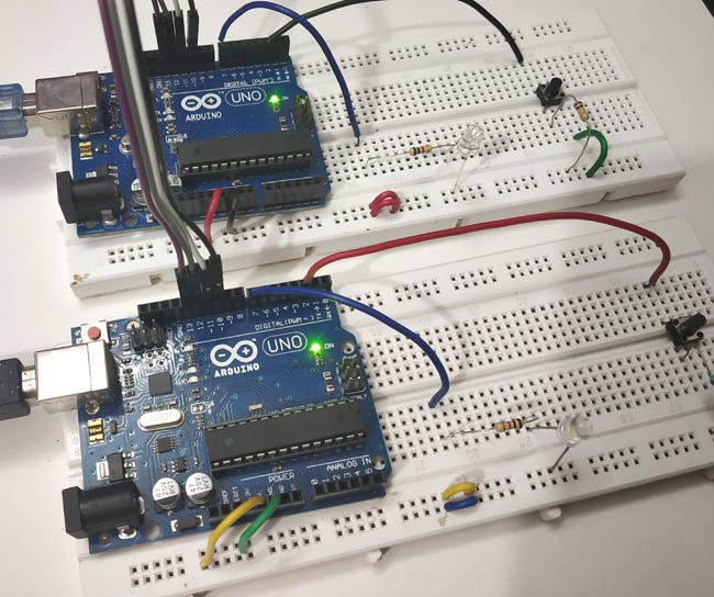

- #TEST SERIAL CONNECTION BETWEEN TWO ARDUINOS FULL#
- #TEST SERIAL CONNECTION BETWEEN TWO ARDUINOS CODE#
It’s important that the NRF24L01 module’s VCC pin is not connected to the Arduino 5v pin as this will damage the NRF24L01 module. To make the connection easier to follow and implement, a pin map showing which pins of the Arduino to which the RF module is connected, is shown below.

Schematicsĭon’t forget that the same component will be used to build both the transmitter and receiver so we only need to replicate this for the receiver too. The NRF24l01’s design is not breadboard friendly, so we will have to connect it to the Arduino with jumper wires.Ĭonnect the components as shown in the schematics below. The schematics for this project is quite simple, all we need to do is to connect the NRF24L01 to the Arduino. The exact components used for this tutorial, as usual, can be bought via the links attached to them. The following components are required to build this project

This dummy data being transferred could be data from sensors in a real life application or signals to get the receiver to perform certain actions. The transmitter sends data at a regular interval to the receiver which displays the received data on the serial monitor. To demonstrate the use of this module with Arduino, we will build a simple transmitter and receiver project. This makes it ideal for projects with long battery life specifications.
#TEST SERIAL CONNECTION BETWEEN TWO ARDUINOS FULL#
This module consumes, less than 14mA in full communication mode and consumes only a few microamps in power down mode. One of the best features of this module, aside from the ease with which it can be used with Arduino and other microcontrollers, is its low power consumption. The module can achieve data rates as high as 2Mbits! and uses a high-speed SPI interface in order to communicate with the Arduino and other kind of microcontroller and development boards. It is designed to operate within the 2.4GHz ISM band which means it can be used for projects with industrial, scientific and medical applications. The NRF24L01 module is a low-cost (less than$3) ultra-low power, bi-directional transceiver module. Today, we will look at the radio frequency based communication between microcontrollers using one of the most popular RF communication modules the NRF24L01 communication module. For mid-range communication between two microcontrollers, for example, one of the most suitable communication protocol is RF (radio frequency) as it has a good cost to performance ratio and a very good communication range can be attained using certain modules. All of these communication protocols have their pros and cons and the situation is in which they are the best fit. For wireless communication between devices, quite a number of options exist including WiFi, GSM/GPRS, Bluetooth, RF and more recent technologies like LoRaWAN among others. This communication could be achieved using either wired or wireless process. While (!Serial) // Leonardo: wait for serial monitorįor(address = 1 address > Serial Monitor) You'll get a message as follows.While building Arduino or any other microcontroller platform project over time the need will arise to establish communication between two of the Arduino boards or microcontrollers for data exchange and/or control. Devices with higher bit address might not be seen properly. This sketch tests the standard 7-bit addresses
#TEST SERIAL CONNECTION BETWEEN TWO ARDUINOS CODE#
You can find the source code for I2C Scanner from official Arduino site. (ex : removing/ adding resistors) When devices with I2C communication, first of all we need to check the I2C addresses of the devices. Often manufacturers provide contingencies to change I2C adresses by doing minor hardware changes. In most of the cases we see that people copy Arduino codes from internet and often say their codes are not working. When using the wire library (for I2C in Arduino) it activates internal pull-up resistors (20k-150k, depending on the pin and the board model) and Mega 2560 board has on board pull up resistors (10k). General rule of thumb is to start from 4.7k Ohms resistors and bring it down depending on the length and the connected devices of the system. I2C bus drives can pull signal lines to ground but they are not capable of driving it to high. Pull up resistors are required when you connect more than two devices to the network. (But in our case, since we use 7 Bit addresses we can theoretically put only 127 slaves, that also may come down depending on the capacitance on the I2C Bus.) Compared to SPI (Serial Peripheral Interface), it has a lower data transfer rate. It supports multiple masters and multiple slaves with only two wires ! Also important to note that we can connect any number of masters and up to 1008 slave devices to an I2C network. I2C communication is a very easy to use synchronous serial communication protocol.


 0 kommentar(er)
